iPod Integration for the 1993 Mustang Factory Stereo
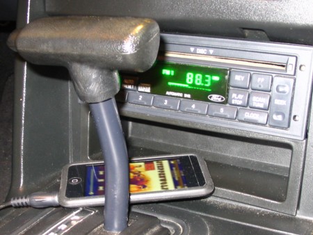
My car has a factory stereo with CD player. The CD Player doesn’t work too well but it’s one of those options that make my car unique. After all, 1993 was the first year for a CD player in a Mustang.
In thinking ahead to my 6 hour trip to Carlisle I wasn’t again looking forward to just FM listening. We all know how that is across a great distance. I thought it will be a good time for an audio book, some podcasts and/or some decent music.
Not wanting to modify my car in any permanent way I needed to come up with a totally reversible solution. I knew I wouldn’t be happy with an FM transmitter solution. I settled on the Scosche FM Modulator (FM-MOD02).
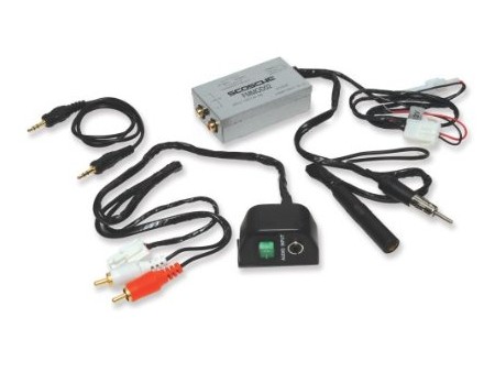
It plugs into the antenna input on the stereo and sends the signal through on one of two FM frequencies. Since it is hard-wired it has an advantage over the FM transmitter type. The reviews on it were very good with most people thinking it played near CD quality sound.
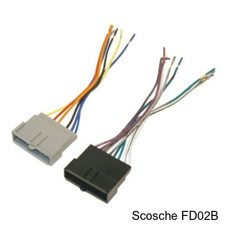
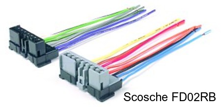
The only challenge was to find a switched power source without splicing into the factory wiring. After failing to find a usable option, what I guessed I needed was an extension for the factory stereo cable that would allow me to splice into it guilt free. I couldn’t find one so I created one. Again I went with Scosche products. I purchased the Scosche FD02B and FD02RB cables. I found both on ebay for pretty cheap.
FD02B is for connecting Ford factory wiring to an aftermarket stereo. FD02RB is for the reverse – connecting some other wiring like that from another car to a Ford factory stereo. So, I thought, why can’t I splice these together? It turns out that I could. And did.
Each Scosche part # came with two cables. One for the stereo power, ground, etc. (gray connector) and the other for the speakers (black connector).
The factory harness for the speakers in my 1993 Mustang with premium sound uses a different speaker connector type than the Scosche one that I got. These speaker cables were for cars without premium sound.
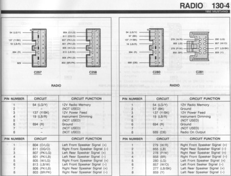
My factory wiring harness was wired just as the 1993 Electrical & Vacuum Troubleshooting Manual (EVTM) documents. I have included it here because it can be hard to find this information if you don’t have the right resources (click on it for a bigger version). And, some of the information out there is wrong. As far as I can tell C257 and C258 are for non-premium sound and C280 and C281 are for premium sound.
The first problem was that the Scosche cable was missing pin #2 but had pin #7 wired. Here it is below. Note: as pictured, pin #1 is on the left.
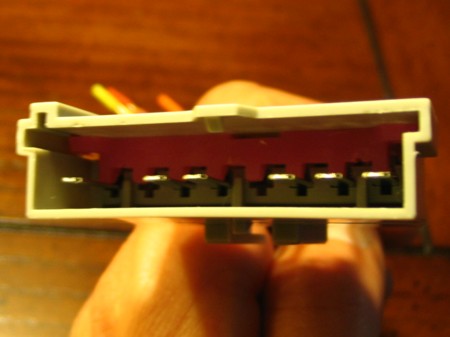
I could not find an easy way to move the pin #7 connector over to pin #2. It looked like it was locked in and would have needed too much force to take it out. Although, the black connector cables for the speakers had all 8 connections wired. So, I chose to go with them not yet realizing a subtle difference between them and the power/ground (gray) connectors. I spliced the wires together. Now, into this extension, I could splice the switched power (pin #3) and ground (pin #6) in order to power the FM Modulator.
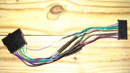
I was feeling pretty proud at this point. But, as I was looking closer at the diagram in the EVTM manual I noticed the tab on one connector that fit into a slot on its counterpart. On the power/ground connectors they were on the opposite side as those on the speaker connectors. These black connector speaker connectors were not going to match up with the gray connector power/ground cable or my stereo. I am sure this is by design so that they can’t get mistakenly interchanged. For me, what a letdown.
Since I didn’t want to waste all that splicing, soldering and heat shrinking work I decided to forge ahead. With a utility knife I was able to trim off the tab on the female connector so that it would mate with my stereo and with a Dremel tool on the male one I cut a slot so it would accept the tab on my factory female cable.
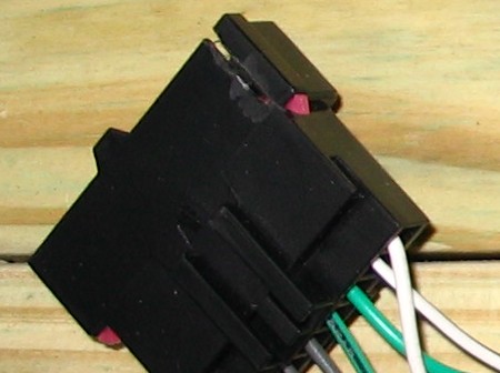
Now the connectors would fit. Almost. The female version had a another small tab on it in the center of one side that looked like it was there to lock into the male end. Only that tab was blocking the cable from inserting into the stereo. Again, I used an utility knife to do some trimming. Even with it trimmed flat, the cable still held tight into the stereo. Phew.
It was a little bit of a pain to get all of that new cable up behind the stereo. Below is a picture of what it looked like just before I put the stereo back in. I have highlighted a few things.
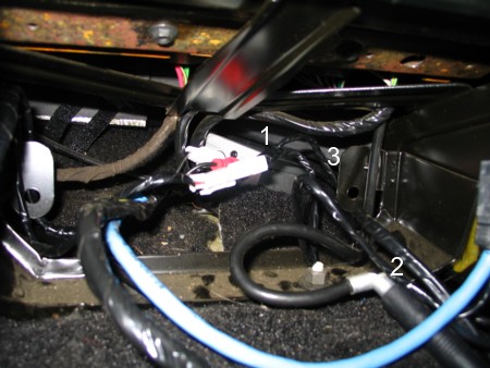
- The FM Modulator box is at the farthest point back that I could get it.
- The factory antenna cable is plugged into the cable from the FM-MOD02.
- Out of sight here is the inline fuse for the FM-MOD02. It is reachable from the passenger’s footwell should the need ever arise.
Not shown in the picture is the stereo with my extension cable attached. I zip tied it to the back so it would remain there as I slid the stereo back. Without it zip-tied, it had a tendency to go under the stereo which created a clearance problem when the stereo was almost all the way back into the dash.
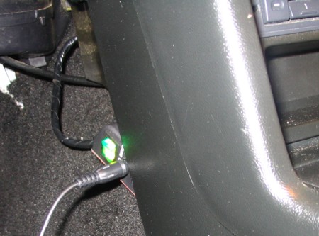
Once everything was installed I now have the small block with the on/off switch and 3.5mm minijack input coming out from behind the dashboard. I opted not to use the double-sided tape that is on the back of it. I can tuck it behind the center of the dash where it is fully out of sight. When I need it, it is easily made available by pulling it part way out. The green of the lighted switch matches the green of my stereo display. Nice.
Very cool additon to the car. I would like to find a factory CD player for my 93 GT. They are a tough find. Though.