Garage Phase 2 – Adding heat
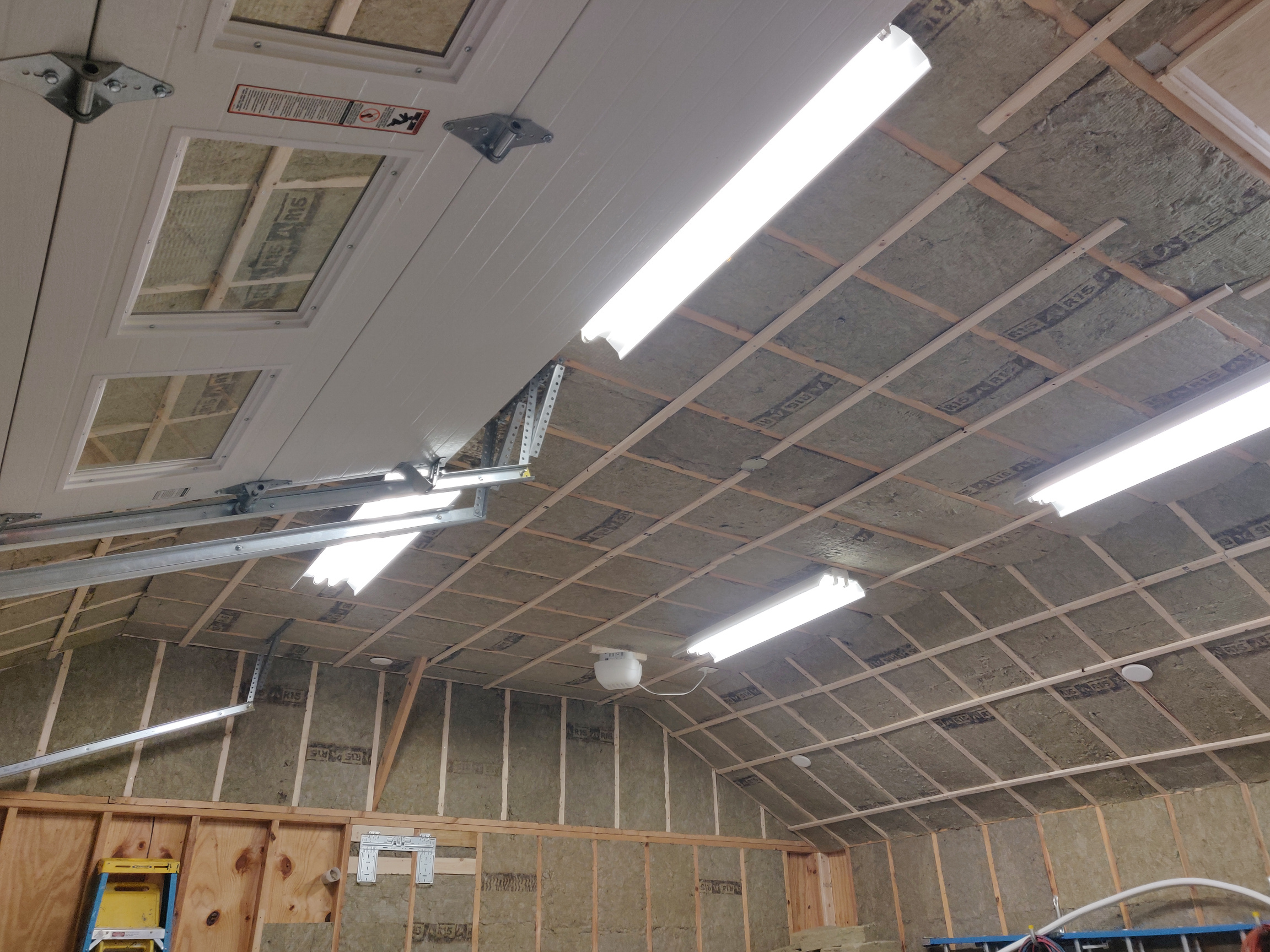
In Part 1, I went through the insulation process. I achieved what I thought was a good enough result for this space – R15 for the walls, R30 for the sloped ceiling and R45 for the rest of the ceiling. Given the heat loss of the garage doors and concrete slab, this seems more than acceptable.
After the insulation install and with winter quickly approaching, I decided to get right to installing a mini split heat pump. There was a long lead up to this step which involved picking what to install. I decided to go DIY as this project would have been too expensive to justify otherwise.
Equipment choice
The conventional choice would be go to the standard DIY option, Mr. Cool. What I found as disadvantages of that option steered me to look elsewhere. These being the fixed length of the line set (at 25 ft.) and the lowest outdoor temperature at which it will heat which is 5°F. While we rarely get temps in my locale in the low single digits or below, I figured a mini split with a lower operating limit would be better in the range that I am looking for it to operate in.
As a result, I choose the Pioneer WYS series as they are still relatively DIY friendly and have an operating limit for heating at -13°F. Like the Mr Cool and many other mini splits, this model has a freeze protection mode. Most mini splits have the ability to heat in the range from the low 60’s upwards to the 80’s or even 90°F’s. The intent of freeze protection mode is to keep your space above freezing in order to prevent frozen pipes during periods when you are away. With the Pioneer, freeze protection mode keeps a constant 46°F. And, there’s no reason you can’t run it in that mode all the time, right? We shall see. Actually, we’ll evaluate the real world performance in a future post on that exact topic.
Sizing
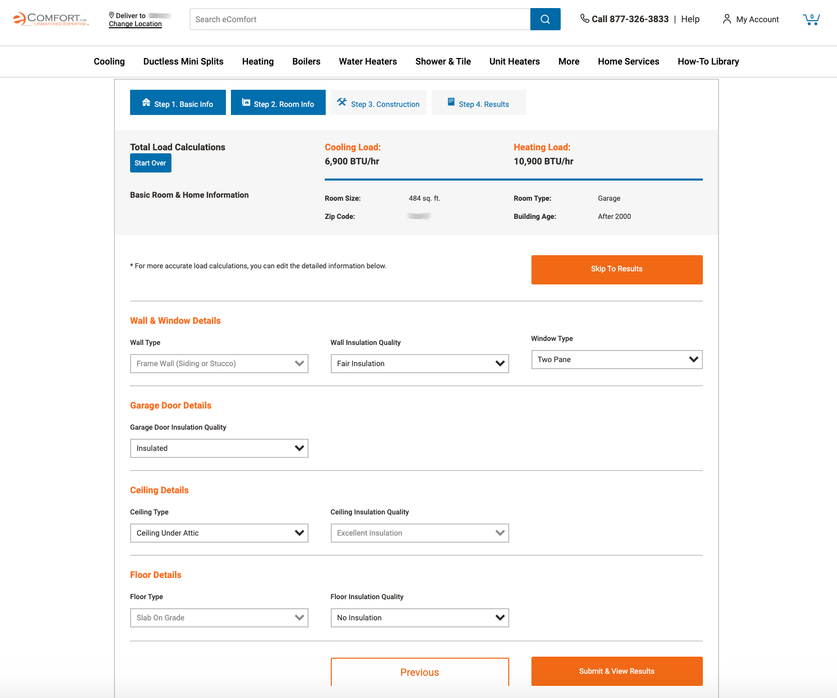
In order to determine sizing of the mini split, you can use a very basic calculation solely based on square feet all the way up to a full calculation based on Manual J. There are calculators that are between these two as well. I found that the complicating factor in using these generic, simplified calculators was that, being a garage, my room was not standard. Any calculations should account for the garage doors, the concrete slab floor and the ceiling height.
I found a good compromise in the calculator here. It allowed me to add the specification that I thought made this complicated but was simple enough for me not being an HVAC pro. It also allowed me to try many what-if choices varying things like design temperature, type of ceiling (because I didn’t know if my tiny attic would qualify as such) and to assess the impacts of keeping the space well heated or just heated enough.
To confirm these findings, I did find a Manual J calculator at coolcalc.com that didn’t seem to require a PhD in HVAC and had a free option that seemed to give me what I needed.
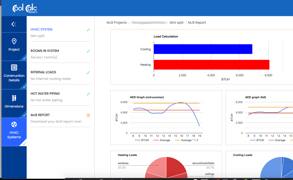
My conclusion was that 12k BTU/hr seemed appropriate for maintaining the heat at 46°F through the winter months. If I decided to use it for cooling in the summer, this size would be appropriate for that as well.
Install process
There are lots of good videos on YouTube to guide you through the install so I won’t cover all those details here. Instead, I plan to cover the things that I wish I knew before I did the install.
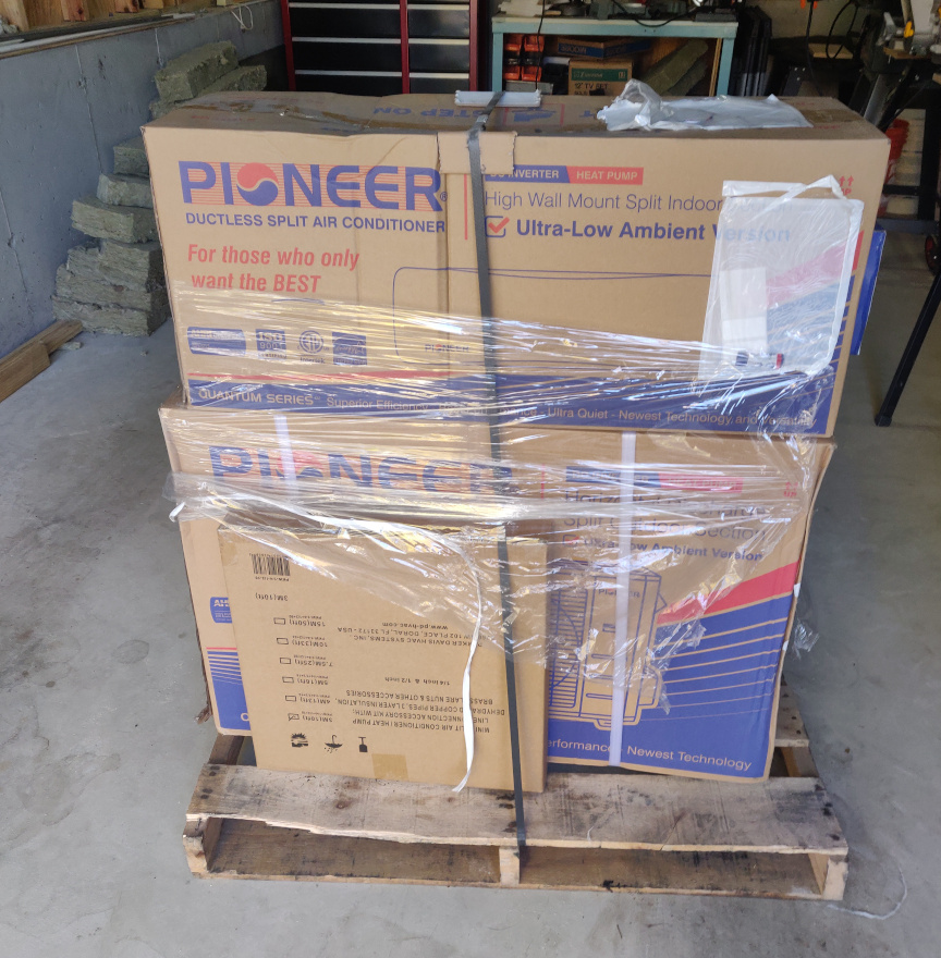
I purchased my unit from Pioneer Mini Split Store. It shipped to me on a pallet and delivery by the shipper was seamless. The driver used a pallet jack to put in right into my garage.
Planning. I spent a lot of time planning the location of both the inside and outside units so that I would not have any coiled line set. I created a cardboard template for the outside unit. This allowed me to position it where I thought I wanted it considering the stud locations required for the mounting bracket. I wanted to get the vertical parts of the wall bracket to be on studs. And, with the walls unfinished, I was later able to install blocking in the wall for the horizontal bracket piece.
I used a couple pieces of twine cut to the length of both the line set and the control wire in order to confirm that my proposed location was good.
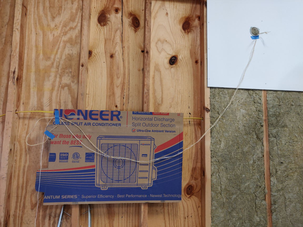
The flaw in this planning was that it was all in the same plane and didn’t take into account that the mini split would be mounted several inches away from the house. Luckily, I had planned for a little extra length at each end for adjustments.
Wifi module. I purchased the Pioneer OSK102 wifi kit from Amazon as I wanted to make sure that I had control of the Mini Split from my phone. More than anything, I wanted the ability to monitor it to see when it was running. This was based on my experience with the Nest thermostat, where that app helped me understand how my choices for temperature mapped to how often and how long our furnace was running (and ultimately allowed me to make money savings changes in how we heated our house). It actually turned out that the Mini split itself came with a wifi module.
Both of these wifi kits were slightly different. The Pioneer OSK102 wifi kit included a module which plugged into the USB port in the circuit board in the front panel of the indoor unit. The Pioneer OSK102 is controlled via the Nethome Plus app. The Pioneer Smart Controller kit (TST-APWIFICWPD), which came with the mini split, is a small circuit board which replaces the existing board under the front panel. It uses the Cielo Home app.
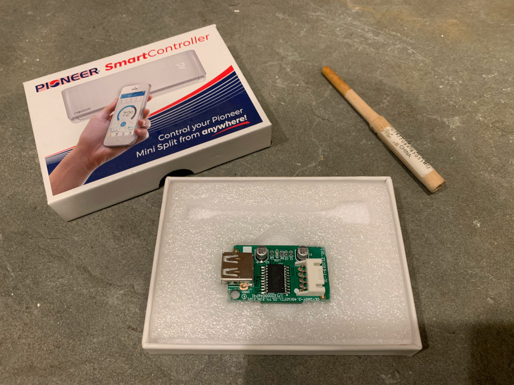
I was able to try both to see which I preferred. I ultimately went with the Pioneer Smart Controller because I thought the app was better. I was not able to figure out how to turn on freeze protection mode with the Nethome Plus App. Since it’s been a couple months since I used it, I honestly can’t remember if the app had that feature but I seem to remember it not having it.
Ultimately, though, the wifi kit turned out to be of very little use to me. It turns out that when the mini split is in freeze protection mode, the Cielo app shows the Mini split as off. As such, the history section of the app shows “No usage” for every single day. So, my hopes for a Nest-like graphic visual of when the heat was on each day were not met.
Vacuum Port Adapter. This is the second thing that I bought that was redundant. The mini split itself came with a vacuum port adapter. This is required to attach the vacuum pump to the mini split. I think that I got this with the mini split that I purchased because it included an installation kit. This may also be the reason for in inclusion of the Pioneer Smart Controller. If you are installing another brand or the Pioneer without the installation kit, you will need this adapter.
Drain plug removal/install. The Pioneer mini split has two places where you can install the drain hose. In order to have the drain hose, line set and control wire exit the mini split on the side required by my installation, I had to use the alternate drain port. This meant I had to remove the factory installed drain plug from the port that I needed open and move it to the currently open port.
The rubber plug is easy to remove but difficult to install. Actually, I tore mine trying to push it into the hole with a nylon tool. It was difficult to get leverage and to compress it into the hole. What I found was that I needed something to push it which I accomplished with a custom tool that I made. I simply took the handle from a foam brush and used my bench sander to taper it to fit into the plug. See the photo above for this tool.
Torquing connections. The torque wrench that I purchased for this project was great for the 1/2″ line which required 26.6 lb-ft of torque. It did not meet the need for the 1/4″ line. While the requirements for this was for 11.8 lb-ft and the wrench had a low setting of 10 lb-ft, it just didn’t work getting to this value so close to it’s lower limit. The adjustment grip on the handle did provide some positive feedback that there was tension as you turned it, but this went away under 12 lb-ft as it just seemed loose. I still moved ahead with the tightening which was difficult with such a small wrench head. I ended up over-tightening as the limit click was never achieved and I straightening the flaring right out of the tubing.
Thankfully, I had purchased a flaring kit as a backup as I had heard that the factory flarings were often imperfect. I was at first pleased that my flarings were all perfect from the factory but then thankful I had this kit so I could add back the flaring I took out of the tubing.
The small and large diameter tubing ends which you connect the line set to on the inside unit were not the same length. This mismatch in length resulted in an equal mismatch on the outside unit. Since I had the flaring kit, it was a no-brainer to cut the 1/4″ tubing by the approximate same difference prior to making the outside connections in order to get everything to look clean. If I had to do it over again, I think I would have cut the extra off the line set where it attached to the inside unit where the lengths of the factory pieces were different and not let that difference transfer all thw way through to the outside unit.
The result
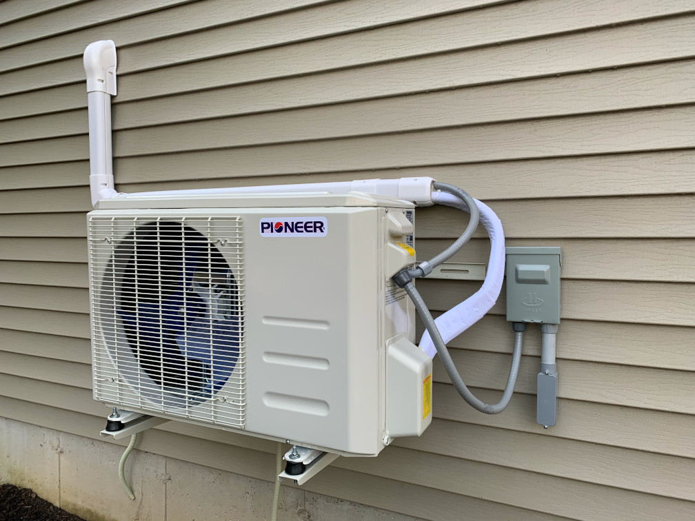
I am very happy with the end result. I got the outside all buttoned up before the cold weather really set in. It was never clear to me how the nylon wrap was supposed to stick to the line set so I ended up zip tying each end.

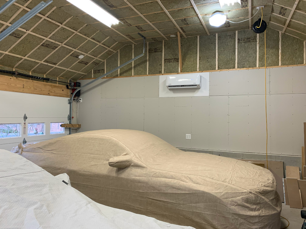
On the inside, I did get unit almost centered on the wall with about 8 feet from it’s bottom to the floor. I primed and painted a piece of drywall for behind the inside unit. I then realized I had enough time left in the fall to work in my newly heated garage to install some drywall on the walls. Since I was working alone, I focused on the lower parts of the walls. The ceiling and upper walls will wait until next year.
Next up, heating usage monitoring.
What I used for this project –
- PIONEER® 12,000 BTU 21.5 SEER 230V DUCTLESS MINI-SPLIT AIR CONDITIONER HEAT PUMP SYSTEM FULL SET
- 3″ DECORATIVE PVC LINE COVER KIT FOR MINI SPLIT AIR CONDITIONERS & HEAT PUMPS
- Outdoor Mounting Bracket for Ductless Mini Split Air Conditioner Heat Pump Systems, Universal, 9000-36000 Btu Condenser
- TEKTON 1/2 Inch Drive Click Torque Wrench (10-150 ft.-lb.) | 24335
- Sunex 9708 3/8-Inch Drive Fractional Crowfoot Flare Nut Wrench Set, 3/8-Inch – 7/8-Inch, Fully Polished, 8-Piece
- Sunex 97730A 1/2″ Dr. 15/16″ Jumbo Crowfoot Wrench CRV
- Wostore Flaring Swage Tool Kit for Copper Plastic Aluminum Pipe With Tubing Cutter & Ratchet Wrench
- Refrigeration Technologies RT201B Nylog Gasket/Thread Sealant
- ZENY 3,5CFM Single-Stage 5 Pa Rotary Vane Economy Vacuum Pump 3 CFM 1/4HP Air Conditioner Refrigerant HVAC Air Tool R410a 1/4″ Flare Inlet Port, Blue
- ZENY Diagnostic A/C Manifold Gauge Set R134a Refrigeration Kit Brass Auto Service Kit 4FT w/Case, 1/4″ SAE Fittings